Precision measurement in electroplating and surface-coating industries confirms that a protective or decorative coating, such as zinc plating, powder coat or anodizing, meets its specified thickness range across the part. Coating thickness gauges using magnetic induction or eddy current methods measure this without damaging the coating, supporting both corrosion-resistance requirements and cosmetic consistency.
Why Precision Measurement Matters in Coating Processes
A coating that is too thin may fail to provide adequate corrosion resistance or meet a customer’s cosmetic specification. A coating that is too thick can affect fit, add unnecessary material cost, or, in some plating processes, indicate an underlying process control problem.
Because coatings are applied in a controlled but variable process, involving bath chemistry, dwell time, current density and part geometry, thickness naturally varies across a part and between batches. Measurement is the only way to confirm that variation stays within an acceptable range.
How Coating Thickness Is Measured
Related: Elektrophysik coating thickness gauges
Magnetic induction gauges measure non-magnetic coatings, such as zinc plating, paint or powder coat, applied over a ferrous substrate like steel. The instrument detects the change in magnetic field caused by the coating’s thickness between the probe and the base metal.
Eddy current gauges measure non-conductive coatings, such as anodizing, applied over non-ferrous substrates like aluminium, using an induced eddy current in the base metal rather than a magnetic field.
Combined-probe instruments detect the substrate type automatically and switch measurement method accordingly, which is useful in operations that process both ferrous and non-ferrous parts.
QC Checkpoints Across the Coating Process
Pre-plating and pre-coating checks confirm the base material and surface preparation meet requirements before coating begins, since surface condition directly affects coating adhesion and consistency.
In-process thickness sampling during production catches drift in bath chemistry, current density or line speed before an entire batch is affected, allowing corrective adjustment mid-run rather than after the fact.
Final release inspection typically involves thickness measurement at multiple defined points on each part, or on a statistically representative sample, documented against the customer’s specification before the batch ships.
Common Applications by Coating Type
Related: coating thickness gauge range
Zinc and zinc-alloy plating on fasteners and structural steel parts is measured to confirm corrosion-protection thickness, typically with magnetic induction gauges.
Powder coating on architectural and automotive components is measured for both cosmetic film build and, in outdoor applications, weather-resistance thickness requirements.
Anodizing on aluminium components, common in aerospace, electronics housings and consumer products, is measured using eddy current methods appropriate to the non-ferrous substrate.
Electroless nickel and other functional coatings used for wear resistance or corrosion protection on precision components are measured to confirm the coating does not push a critical dimension out of tolerance.
Common Mistakes in Coating Thickness Inspection
Using the wrong measurement method for the substrate, such as applying a magnetic gauge to a non-ferrous part, is one of the most common errors and produces meaningless readings.
Measuring too close to an edge or corner can give an inaccurate result, since coating build-up and instrument response both behave differently near part edges than on a flat surface.
Failing to account for substrate curvature or thickness in gauge calibration can introduce systematic error, particularly on thin-walled or small-diameter parts.
Building Coating Inspection into a Quality System
A documented coating-thickness sampling plan, specifying how many points are measured per part, where those points are located, and how results are recorded, keeps inspection consistent between operators and between shifts.
Where a customer specification calls for a minimum and maximum thickness range, recording individual point readings rather than only a pass/fail result gives the process team the data needed to spot a drifting trend before it produces an out-of-specification batch.
Statistical Process Control for Coating Thickness
Because coating thickness varies naturally within a process, tracking individual readings over time using statistical process control (SPC) gives far more insight than a simple pass or fail check at final inspection. Plotting thickness readings on a control chart makes a gradual drift, such as a slowly depleting plating bath, visible well before it produces an out-of-specification part.
SPC also supports process capability studies, which compare the natural variation in a coating process against the specification width to confirm the process is capable of consistently meeting the requirement, not just passing on a given day.
Standards Commonly Referenced in Coating Specifications
Coating thickness requirements in industry are generally set with reference to recognised international or national standards, which define measurement method, minimum sample size, and reporting requirements for a given coating type and substrate combination.
The specific standard that applies depends on the coating type, the industry, and the customer’s own quality requirements. Confirming the exact standard referenced on a purchase order or drawing before setting up an inspection plan avoids building a sampling routine that does not match what the customer actually expects to see in the inspection report.
Handheld vs Automated Inline Measurement Stations
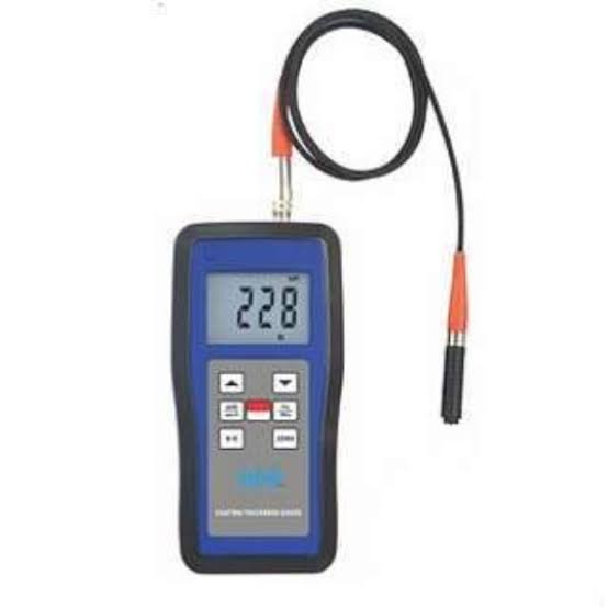
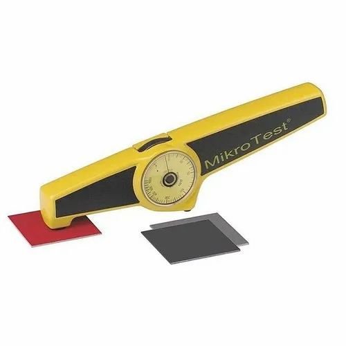
Handheld coating thickness gauges are the most flexible option, suited to spot checks, small batch runs, and parts of varying shape and size where a fixed measurement station would be impractical. They are also the standard choice for field verification away from the production line.
Automated or inline measurement stations, built into a production line, can check every part rather than a sample, and are generally used in high-volume operations where 100 percent inspection is required or where manual handheld checks would create a bottleneck. The trade-off is a higher capital cost and typically less flexibility to handle varied part geometries compared to a handheld gauge.
Many operations use both: automated inline checks for full-batch coverage on a primary part family, with handheld gauges kept available for new parts, low-volume runs, and troubleshooting when an inline reading looks unexpected.
Environmental and Surface Factors That Affect Readings
Surface roughness on the base material can affect coating thickness readings, particularly with magnetic induction gauges, since a rough substrate can cause the probe to sit slightly differently than it would on a smooth surface. Some instruments allow a roughness correction factor to be applied; where this is not available, taking multiple readings and averaging reduces the impact.
Ambient temperature and probe cleanliness also affect reading stability. A probe tip contaminated with coating residue or debris from a previous measurement can produce a falsely high or inconsistent reading, so wiping the probe tip periodically during a measurement session is good practice, particularly in a high-throughput inspection routine.
Common Coating Types Used Across Industry
Zinc and zinc-alloy electroplating remains one of the most widely applied coatings for corrosion protection on steel fasteners, brackets and structural components, valued for its relatively low cost and well-established process control.
Powder coating provides a durable, decorative and protective finish widely used on architectural aluminium, automotive trim and consumer goods, applied as a dry powder and then cured under heat rather than as a wet paint film.
Anodizing, an electrochemical process that thickens the natural oxide layer on aluminium, is valued for its hardness, corrosion resistance and ability to accept dye for decorative colour, and is common in aerospace, electronics enclosures and architectural aluminium.
Exact target thickness ranges differ by coating type, substrate, and the specific application’s functional or cosmetic requirement, and should always be confirmed against the relevant specification or drawing rather than assumed from general industry practice.
Choosing Between Contact and Non-Contact Measurement Methods
Magnetic induction and eddy current gauges, the two methods covered earlier in this article, are both contact methods, meaning the probe physically touches the coated surface during measurement. They remain the standard choice for most coating thickness applications because of their speed, portability and non-destructive operation.
For some specialised applications, particularly very thick coatings, multi-layer coating stacks, or surfaces where contact is undesirable, non-contact optical or ultrasonic methods are used instead. These generally involve higher equipment cost and are reserved for cases where a contact gauge cannot deliver the required measurement resolution or where physical contact risks marking a finished cosmetic surface.
Root Cause Analysis When Coating Thickness Fails Specification
When a batch fails coating thickness inspection, a structured root cause approach generally works through the process in sequence rather than jumping to conclusions. Start by confirming the measurement itself is reliable, checking gauge calibration and probe condition, before assuming the coating process is genuinely out of specification.
If the measurement is confirmed accurate, the next step is reviewing process parameters around the time the affected parts were produced, such as bath concentration, current density, dwell time or cure temperature, depending on the coating type, since a shift in any of these is the most common root cause of an out-of-specification batch.
Part geometry can also be a contributing factor. Recessed areas, sharp edges and corners often receive different coating thickness than flat surfaces in the same process, so confirming whether failures cluster at specific part features, rather than occurring randomly, often points directly to a fixturing or process-geometry issue rather than a fundamental process control problem.
Training and Consistency Across Operators
Because probe angle, contact pressure and measurement point selection all influence a coating thickness reading to some degree, operator technique meaningfully affects result consistency, particularly on curved or textured surfaces. Structured training on correct probe handling and a documented reference for where to take readings on each part reduces operator-to-operator variation.
Periodically cross-checking readings between operators on the same sample part is a simple, low-cost way to confirm the inspection process remains consistent across shifts, and to catch a developing technique problem before it affects a significant number of parts.
Choosing a Coating Thickness Gauge for Your Facility
The starting point for selecting a coating thickness gauge is confirming the substrate and coating combinations your facility actually processes. A plant working only with steel and zinc plating may only need a magnetic induction gauge, while a facility processing both ferrous and non-ferrous parts, such as steel and aluminium components in the same line, is generally better served by a combined-probe instrument that handles both automatically.
Batch size and part variety matter too. A facility running large volumes of a small number of part families may find an automated inline station justifies its higher cost, while a facility handling varied, lower-volume work is usually better served by one or more portable handheld gauges that can move between part types without a fixed setup.
Finally, consider what documentation and data output the gauge needs to support. Facilities working to formal customer specifications generally benefit from instruments that can log individual readings for SPC analysis and export records for inspection reports, rather than a basic display-only gauge that requires readings to be transcribed manually.
Calibration and Verification of Coating Thickness Gauges
Coating thickness gauges should be verified regularly against certified reference foils or shims of known thickness on the same base metal type being measured in production, since verifying on the wrong substrate type can mask an instrument problem rather than catch it.
Many facilities check a gauge at the start of a shift and periodically during a production run, in addition to formal calibration at accredited intervals, since day-to-day verification against a reference standard is the fastest way to catch a probe that has become damaged or contaminated during use before it produces a run of unreliable readings.
The main QC checkpoints in a coating process are pre-plating surface preparation, in-process thickness sampling, and final release inspection. Each checkpoint typically uses a different level of measurement rigour, from spot checks during production to full documented thickness mapping before a batch is released to the customer.
FAQs
Why is coating thickness measurement important in electroplating?
Coating thickness directly affects corrosion resistance, cosmetic appearance and, in some cases, fit and function. Measuring it confirms the plating or coating process is delivering a consistent, specification-compliant result across every part.
What instruments measure dry film thickness (DFT) on coated parts?
Magnetic induction gauges measure non-magnetic coatings on ferrous substrates, while eddy current gauges measure non-conductive coatings on non-ferrous substrates. Combined-probe instruments can handle both, depending on the substrate detected.
Can coating thickness be measured without damaging the part?
Yes. Magnetic induction and eddy current methods are non-destructive, measuring coating thickness through the coating itself without removing or cutting into it.
How often should coating thickness be checked during production?
Checkpoint frequency depends on the process and specification requirements, but typically includes in-process sampling during a production run and a final measurement pass before batch release. Exact intervals should follow your quality system.
What causes inconsistent coating thickness readings on the same part?
Common causes include measuring too close to an edge, using the wrong probe type for the substrate, or not accounting for part curvature during gauge calibration. Checking multiple points away from edges generally gives a more representative result.
Is anodizing measured the same way as zinc plating?
No. Anodizing on aluminium is measured with an eddy current method suited to non-ferrous substrates. Zinc plating on steel is measured with a magnetic induction method suited to ferrous substrates.
Should I use a handheld or an automated inline coating thickness gauge?
Handheld gauges suit spot checks, small batches and varied part shapes. Automated inline stations suit high-volume lines needing full-batch inspection. Many operations use both, depending on the part family and volume.
Can surface roughness affect a coating thickness reading?
Yes, particularly with magnetic induction gauges, since a rough substrate can change how the probe contacts the surface. Some instruments support a roughness correction factor, or multiple readings can be averaged to reduce the effect.
What is the difference between contact and non-contact coating thickness measurement?
Contact methods, such as magnetic induction and eddy current, physically touch the coated surface and are the standard choice for most applications. Non-contact optical or ultrasonic methods are reserved for very thick coatings, multi-layer stacks, or surfaces where contact is undesirable.
What should we check first if a coating batch fails thickness specification?
Confirm the measurement itself is reliable first, checking gauge calibration and probe condition, before assuming the coating process is out of specification. Then review process parameters such as bath concentration, current density or cure temperature around the time affected parts were produced.
How should a coating thickness gauge be verified day to day?
Check it against certified reference foils or shims of known thickness on the same base metal type used in production, ideally at the start of a shift and periodically during a run, in addition to formal accredited calibration.
What factors should guide the choice between a handheld and an automated coating gauge?
Consider the substrate and coating combinations processed, batch size and part variety, and what documentation the gauge needs to support. High-volume single-family lines often justify automated stations; varied lower-volume work usually favours handheld gauges.
Why should coating thickness readings be logged individually rather than as a pass or fail only?
Recording individual point readings gives the process team the data needed to spot a drifting trend, such as a slowly depleting plating bath, before it produces an out-of-specification batch, which a simple pass or fail result would not reveal.
Request a Quote — Contact BTSA for product selection guidance and calibration support.